


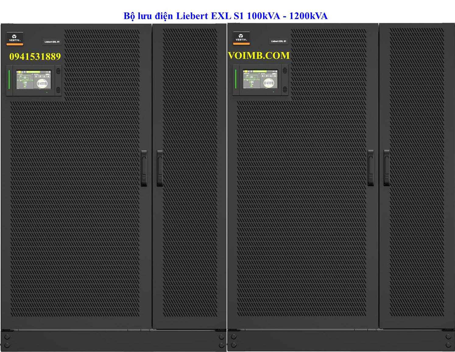
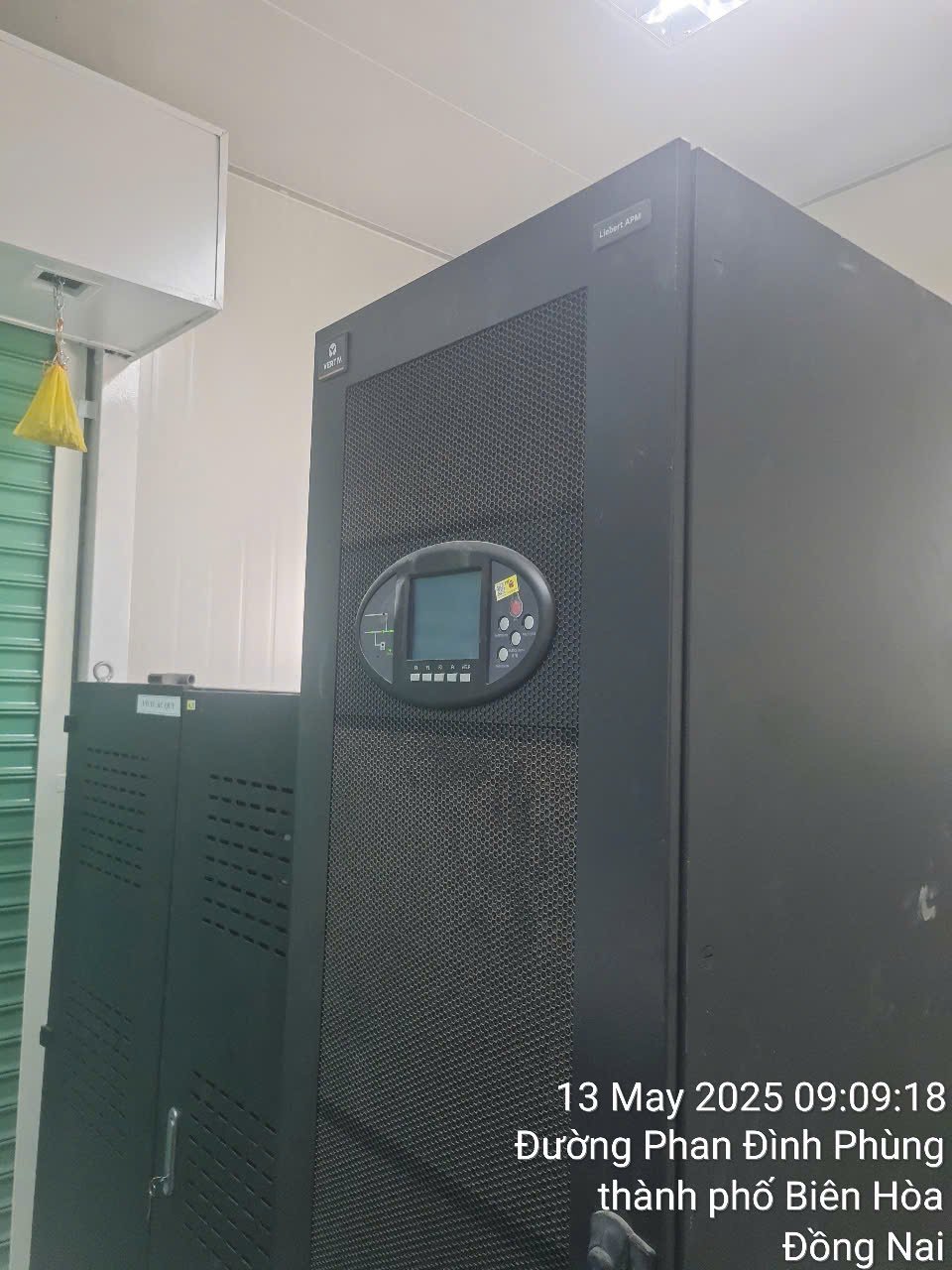
Liebert EXL S1 100kVA - 1200kVA
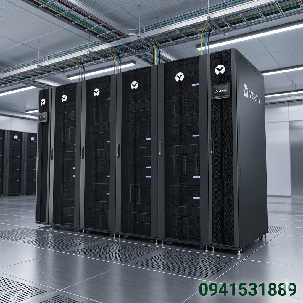
Bộ lưu điện Liebert EXL S1 là một giải pháp năng lượng cao cấp của Vertiv, được thiết kế chuyên biệt cho các trung tâm dữ liệu, cơ sở hạ tầng quan trọng và các ứng dụng công nghiệp. Đây là dòng UPS 3 pha với công suất lớn, tập trung vào hiệu suất năng lượng, mật độ công suất cao và khả năng mở rộng linh hoạt.
Technical Data Liebert EXL S1 (100 to 1200 kW) |
||||||||||||
| UPS UNIT | 100 | 120 | 160 | 200 | 300 | 400 | 500 | 600 | 800 | 1000 | 1200 | |
1 Primary Input |
||||||||||||
| Nominal voltage(3) | (V) | 400 (3Ph or 3Ph + N)(3) | ||||||||||
| Input voltage range w/o battery discharge | (V) | 200 to 460 | ||||||||||
| Nominal frequency | (Hz) | 50 (60 selectable) | ||||||||||
| Power factor @ nominal load & nominal input conditions(2) | ≥ 0.99 | |||||||||||
| Input current distortion @ nominal input conditions(2) & max input current(5) | (%) | ≤3 | ||||||||||
| Walk in/Soft start | (seconds) | 15 (1 to 90 selectable) | ||||||||||
| Rectifier Hold-Off | (seconds) | 10 (1 to 90 selectable) | ||||||||||
| Inrush current / Imax input | ≤1 | |||||||||||
| 2 Battery | ||||||||||||
| Permissible battery voltage range | (V) | 396 to 700 | ||||||||||
| Recommended no. of cells: | ||||||||||||
| - VRLA | 240-300 | |||||||||||
| - WET | 240-300 | |||||||||||
| - NiCd | 375-468 | |||||||||||
| VRLA float voltage for VRLA @ 20°C | (V/cell) | 2.27 | ||||||||||
| End cell voltage for VRLA | (V/cell) | 1.65 | ||||||||||
| Float voltage temperature compensation | -0.11% per °C | |||||||||||
| DC ripple current in float mode for a 10 min autonomy as per VDE0510(5) | <0.05C10 | |||||||||||
| Float Voltage stability in steady state condition | (%) | ≤1 | ||||||||||
| DC ripple voltage without battery | (%) | ≤1 | ||||||||||
| Optimum battery temperature | (°C) | 15 to 25 | ||||||||||
| Battery recharge current setting range for 240 cells @ 400V input voltage & nominal output load(2) | (A) | Up to 27 | Up to 33 | Up to 44 | Up to 55 | Up to 82 | Up to 109 | Up to 137 | Up to 162 | Up to 204 | Up to 270 | Up to 312 |
| Battery recharge current setting range
for 264 cells @ 400V input voltage & maximum output load (PF=1)(2) |
(A) | Up to 8 | Up to 10 | Up to 13 | Up to 17 | Up to 25 | Up to 34 | Up to 42 | Up to 48 | Up to 53 | Up to 80 | Up to 85 |
| Battery Switch | Not included | |||||||||||
| Remote Battery Disconnect | Optional | |||||||||||
| UPS UNIT | 100 | 120 | 160 | 200 | 300 | 400 | 500 | 600 | 800 | 1000 | 1200 | |
Inverter Output |
||||||||||||
| Nominal apparent power | (kVA) | 100 | 120 | 160 | 200 | 300 | 400 | 500 | 600 | 800 | 1000 | 1200 |
| Nominal active power | (kW) | 90 | 108 | 144 | 180 | 270 | 360 | 450 | 540 | 720 | 900 | 1080 |
| Nominal output current | (A) | 144 | 173 | 231 | 289 | 433 | 577 | 722 | 866 | 1155 | 1443 | 1732 |
| Maximum output active power @35°C | (kW) | 100 | 120 | 160 | 200 | 300 | 400 | 500 | 600 | 800 | 1000 | 1200 |
| Overload capacity(6) | 110% continuous, 125% for 10mins, 150% for 1min | |||||||||||
| Short circuit current for 200ms | 2.2In | |||||||||||
| Nominal output voltage | (V) | 400 (3Ph or 3Ph + N) | ||||||||||
| Nominal output frequency | (Hz) | 50 (60 selectable) | ||||||||||
| Voltage
stability in steady state condition for input (AC & DC) variations and step load (0 to Nominal load) |
(%) | ±1 | ||||||||||
| Voltage stability in dynamic condition for input variation (AC & (%) | Complies with IEC/EN 62040-3, Class 1 DC) and step load | |||||||||||
| Voltage stability in steady state for 100% load imbalance (0, 0, 100) | (%) | ±3 | ||||||||||
| Output frequency stability | ||||||||||||
| - synchronized with bypass mains | (%) | ±2 (1, 2, 3, 4, 5 selectable) | ||||||||||
| - synchronized with internal clock | (%) | ±0.1 | ||||||||||
| Frequency slew rate | (Hz/sec) | <1 Default (selectable up to 5Hz) | ||||||||||
| Output voltage distortion at nominal linear load | (%) | <1.5 | ||||||||||
| Output voltage distortion @ reference non linear load as for IEC/EN 62040-3 | (%) | <5 | ||||||||||
| Load crest factor handled without derating the ups | (Ipk/Irms) | 3:1 | ||||||||||
| Phase angle precision with balanced loads | (degrees) | ±1 | ||||||||||
| Phase angle precision with 100% unbalanced loads | (degrees) | ±3 | ||||||||||
| UPS UNIT | 100 | 120 | 160 | 200 | 300 | 400 | 500 | 600 | 800 | 1000 | 1200 | |
Static Bypass |
||||||||||||
| Nominal bypass voltage(3) | (V) | 400 (3Ph or 3Ph + N)(3) | ||||||||||
| Nominal frequency | (Hz) | 50/60 (selectable) | ||||||||||
| Frequency range | (%) | ±1 (2, 3, 4 selectable) | ||||||||||
| Voltage range | (%) | ±10 (5 to 15 selectable) | ||||||||||
| Maximum overload capacity | ||||||||||||
| For 10 minutes | (%) | 125 | ||||||||||
| For 1 minute | (%) | 150 | ||||||||||
| For 600 milliseconds | (%) | 700 | ||||||||||
| For 100 milliseconds | (%) | 1000 | ||||||||||
| SCR I2t @ Tvj=125°C; 10ms | (kA2s) | 125 | 320 | 1201 | 2530 | 5611 | ||||||
| SCR ITSM @ Tvj=125°C; 10ms | (A) | 5000 | 8000 | 15500 | 22500 | 33500 | ||||||
| Prospective short circuit current Icp(7) | (kA) | 35 | 35 | 50 | 100 | 100 | ||||||
| Transfer time whit inverter synchronous to bypass: | ||||||||||||
| - Inverter to Bypass | (ms) | no break | ||||||||||
| - Bypass to Inverter | (ms) | <2ms | ||||||||||
| Default transfer delay time (inverter to bypass) | (ms) | <20 with inverter not synchronous to Bypass | ||||||||||
| Maintenance Bypass | ||||||||||||
| Manual Maintenance Bypass | Included | Not Included - to be considered as an external solution | ||||||||||
| UPS UNIT | 100 | 120 | 160 | 200 | 300 | 400 | 500 | 600 | 800 | 1000 | 1200 |
SYSTEM DATA |
|||||||||||
| AC/AC efficiency VFI without charging current nominal input conditions (1) (2) with resistive load: | |||||||||||
| 25% load | 96.4 (%) | 96.4 (%) | |||||||||
| 50% load | 96.8 (%) | 96.6 (%) | |||||||||
| 75% load | 96.7 (%) | 96.5 (%) | |||||||||
| 100% load | 96.3 (%) | 96.1 (%) | |||||||||
| AC/AC efficiency with dynamic online (VI) without charging current @ nominal input conditions(1) (2) with maximum resistive load: | Up to 99% | Up to 99% | |||||||||
| AC/AC efficiency in Intelligent ECO mode without charging current @ nominal input conditions(1)(2) with maximum resistive load: | Up to 99% | Up to 99% | |||||||||
| Heat dissipation @ nominal input conditions and nominal output load: | |||||||||||
| kW | 3.5 | 4.1 | 5.5 | 6.9 | 10.4 | 13.8 | 17.3 | 21.9 | 29.2 | 36.5 | 43.8 |
| Float mode VFI Btu/h | 11799 | 14158 | 18900 | 23600 | 35400 | 47200 | 59000 | 74780 | 99700 | 124600 | 149500 |
| ECO kW | 0.8 | 1 | 1.3 | 1.6 | 2.4 | 3.2 | 4 | 4.8 | 7.3 | 9.1 | 10.9 |
| Btu/h | 2752 | 3302 | 4403 | 5503 | 8255 | 11007 | 13759 | 16510 | 24791 | 30988 | 37186 |
| Noise @ 1 metre(1)(2) as per ISO 3746 (dBA ± 2dBA) | 65 | 66 | 68 | 69 | 71 | 73 | 76 | 78 | |||
| Noise @ 1 metre(1)(2) as per ISO 3746 (dBA ± 2dBA) | 64 @ partial load |
65 dBA @partial load | 70 @ partial load |
72 @ partial load |
|||||||
| Protection degree with open doors | IP 20 | ||||||||||
| Mechanical dimensions: | |||||||||||
| Height (mm) | 1950 | ||||||||||
| Width (mm) | 500 | 750 | 1000 | 1250 | 1600 | 2000 | 2650 | ||||
| Depth (mm) | 900 | ||||||||||
| No. of cabinets | 1 | ||||||||||
| Frame colour (RAL scale) | 7021 | ||||||||||
| Net Weight (kg) | 370 | 510 | 725 | 990 | 1135 | 1550 | 2275 | ||||
| Floor area (m2) | 0.45 | 0.68 | 0.9 | 1.13 | 1.8 | 2.39 | |||||
| Floor loading (kg/m2) | 822 | 704 | 806 | 844 | 861 | 952 | |||||
| Cable entry | Bottom (Top entry available as an option) | Top/Bottom | |||||||||
| Access | Front and Top | ||||||||||
| Cooling 14.7 Environmental |
Forced Ventilation, front air intake, top air outlet | ||||||||||
| Location | Indoor (free from corrosive gases and conductive dust) | ||||||||||
| Operating Temperature (°C) | 0-40 | ||||||||||
| Maximum relative humidity @ 20°C (non condensing) (%) | up to 95 | ||||||||||
| Max altitude above sea level without derating (m) | 1000 (for higher altitudes complies with IEC/EN 62040-3) | ||||||||||
| Immunity to electrical interference | IEN / EN 62040-2 | ||||||||||
| EMC Class | IEN / EN 62040-2 Class C3 | ||||||||||
| Note: (1) For tolerance
see IEC/EN 60146-1-1 or DIN VDE 0558. The data refer to 25°C ambient
temperature (2) At nominal voltage, nominal frequency (3) In case of a split input configuration, the primary input and the bypass input must have a common neutral reference (4) Referred to derated load conditions (5) With input voltage at nominal value and Voltage Distortion THDv ≤ 1% (6) Value obtained at 25°C (7) Values with fuses, for additional information please refer to User Manual |
|||||||||||
Technical Data Main Static Switch
| MSS TECHNICAL SPECIFICATION | 1000A | 2000A | 3000A | 4000A | 5000A |
| Electrical Data | |||||
| Nominal current (A) | 1000 | 2000 | 3000 | 4000 | 5000 |
| Power @380 V (kVA) | 658 | 1316 | 1975 | 2633 | 3291 |
| Power @400 V (kVA) | 693 | 1386 | 2078 | 2771 | 3464 |
| Power @415 V (kVA) | 719 | 1437 | 2156 | 2875 | 3594 |
| Nominal voltage (selectable) (V) | 400 (380/415) | ||||
| Nominal frequency (selectable) (Hz) | 50 (60) | ||||
| Voltage range (selectable) (%) | ± 10 (± 15) | ||||
| Frequency range (selectable) (%) | ±1 (2, 3, 4 selectable) | ||||
| Maximum operating voltage range (V) | 350 - 460 | ||||
| Maximum overload capacity | |||||
| for 10min (%) | 125 | ||||
| for 1min (%) | 150 | ||||
| for 600ms (%) | 500 | ||||
| for 100ms (%) | 700 | ||||
| SCR I2t @ Tvj= 125°C; 8.3-10 ms (A2s) |
4 5*10⁶ | 16.2*10⁶ | 36*10⁶ | ||
| Itsm @ Tvj=125°C; 10 ms (kA) | 30 | 57 | 85 | ||
| Withstand rating (kA)(1) | 50 | 85 | |||
| ECO mode Efficiency (%) | >99 | ||||
| <0.5 (no break) | |||||
| Transfer time when in synchro | |||||
| Inverter to reserve (ms) | <0.5 (no break) | ||||
| Reserve to inverter (ms) | <0.5 (no break) | ||||
| Transfer time without synchro (ms) | <20 (selectable 0 to 20 ms) | ||||
| Retransfer delay(s) | 5 | ||||
| SYSTEM DATA | |||||
| Noise @ 1 meter as per ISO 3746 (dBA ± 2dBA) | 64 | 70 | |||
| Protection degree with open door | IP 20 | ||||
| Mechanical dimensions: | |||||
| Height (mm) | 1950 | ||||
| Width (mm) | 1025 | 2422 | |||
| Depth (mm) | 910 | ||||
| Weight (kg) | 355 | 845 | 1120 | ||
| Switches | Not included | ||||
| Floor area (m2) | 0.87 | 2.05 | |||
| Floor loading (kg/m2) | 407 | 412 | 546 | ||
| Cable entry | Top / Bottom | Top / Bottom | |||
| Access | Front and Top | ||||
| Ventilation | Forced Ventilation (air flow front/bottom to top) | ||||
| Air flow (only when SCR are ON) (m3/h) | 1130 | 5000 | |||
| Frame color (RAL scale) | 7021 | ||||
| Environmental Data | |||||
| Operating Temperature (°C) | 0 - 40 | ||||
| Maximum relative humidity @ 20°C (non-condensing) (%) | Up to 95% | ||||
| Max altitude above sea level without derating (m) | 1000 m (for higher altitudes complies with IEC/EN 62040-3) | ||||
| Note: (1) With optional fuses (2) Central MSS cabinet only (3) Including handle (4) Top and bottom cable entry through TCE cabinets |
|||||
Ứng dụng cụ thể của Liebert EXL S1
Với những tính năng ưu việt, Liebert EXL S1 được sử dụng để bảo vệ nguồn điện cho các tải trọng yếu trong nhiều ngành công nghiệp.
1. Trung tâm dữ liệu vừa và lớn
Liebert EXL S1 là giải pháp lý tưởng cho các trung tâm dữ liệu và phòng máy chủ, bảo vệ các hệ thống máy chủ, lưu trữ và mạng. Khả năng hoạt động song song giúp đảm bảo tính sẵn sàng cao, đáp ứng yêu cầu của hạ tầng Tier-III.2. Công nghiệp và sản xuất
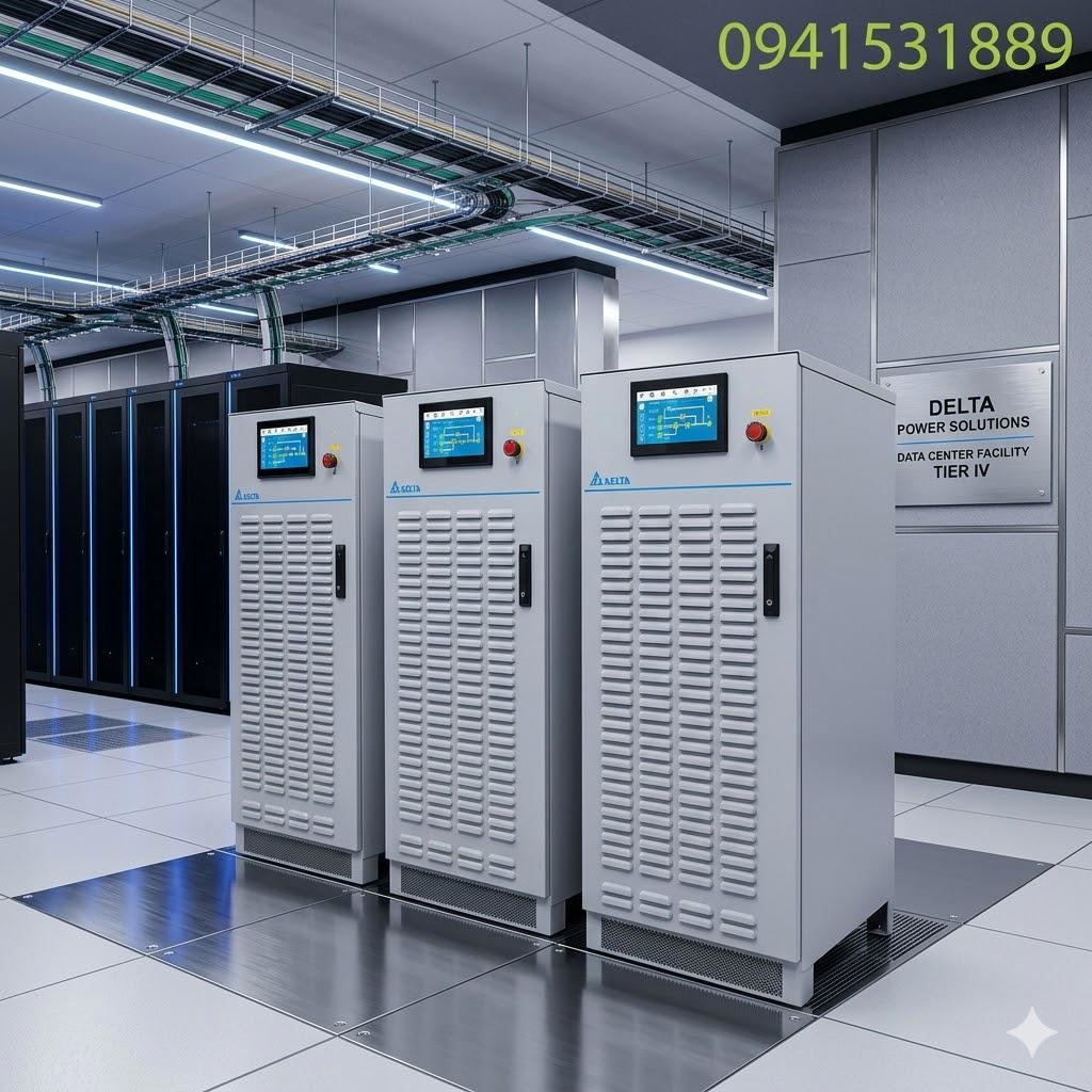
Bảo vệ các dây chuyền sản xuất tự động hóa, các hệ thống điều khiển công nghiệp (PLC), nơi một sự cố điện dù nhỏ cũng có thể gây ra thiệt hại lớn.3. Tài chính và ngân hàng
Cung cấp nguồn điện ổn định cho các máy chủ giao dịch, các hệ thống cơ sở dữ liệu và các hệ thống mạng của các tổ chức tài chính, ngân hàng.4. Y tế
Bảo vệ các thiết bị y tế quan trọng như máy MRI, máy CT scan, và các thiết bị hỗ trợ sự sống, đảm bảo chúng hoạt động liên tục, an toàn cho bệnh nhân.| MODEL | Rating (kW) |
| Liebert EXL S1/100 | 100 |
| Liebert EXL S1/120 | 120 |
| Liebert EXL S1/160 | 160 |
| Liebert EXL S1/200 | 200 |
| Liebert EXL S1/300 | 300 |
| Liebert EXL S1/400 | 400 |
| Liebert EXL S1/500 | 500 |
| Liebert EXL S1/600 | 600 |
| Liebert EXL S1/800 | 800 |
| Liebert EXL S1/1000 | 1000 |
| Liebert EXL S1/1200 | 1200 |
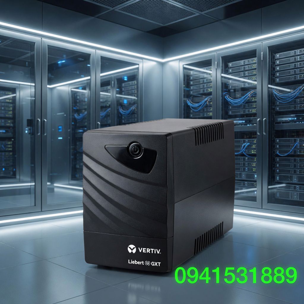
Bộ lưu điện UPS 600VA
Hotline: 0941531889
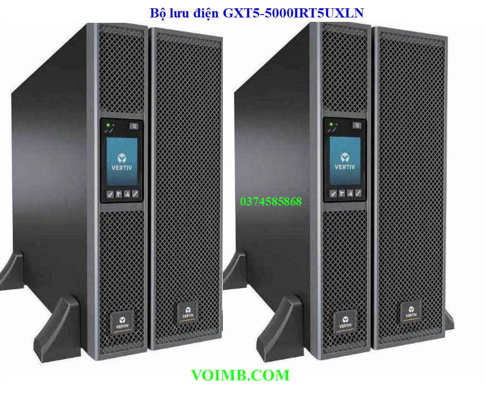
Bộ lưu điện GXT5-5000IRT5UXLN
Bộ lưu điện Liebert GXT5 On-Line 5000VA/5000W 230V LCD PF1.0 5U Extended Run Rack/Tower, RDU101 webcard and Rail Kit Bundled (model GXT5-5000IRT5UXLN)
Bộ Lưu Điện GXT5-10KIRT5UXLN
Bộ Lưu Điện GXT5-6000IRT5UXLN
Bảo hành 03 Năm
Hàng đang có sẵn
Bộ Lưu Điện Liebert APM 150kVA
Hotline: 0941531889
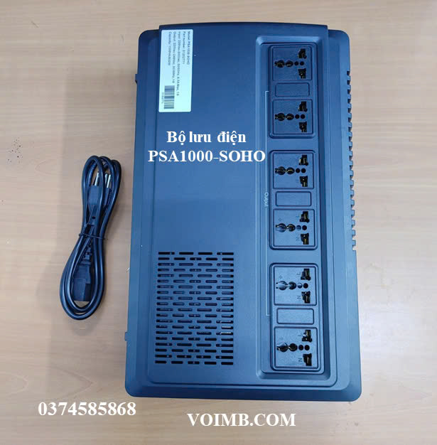
Bộ lưu điện PSA1000-SOHO
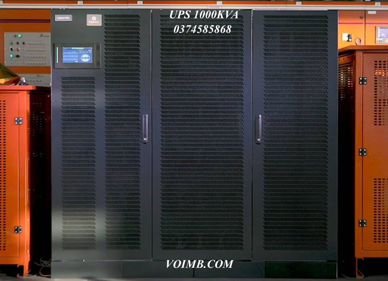
UPS 1000KVA
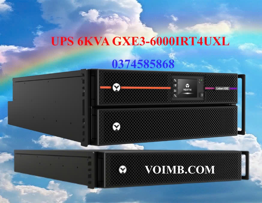
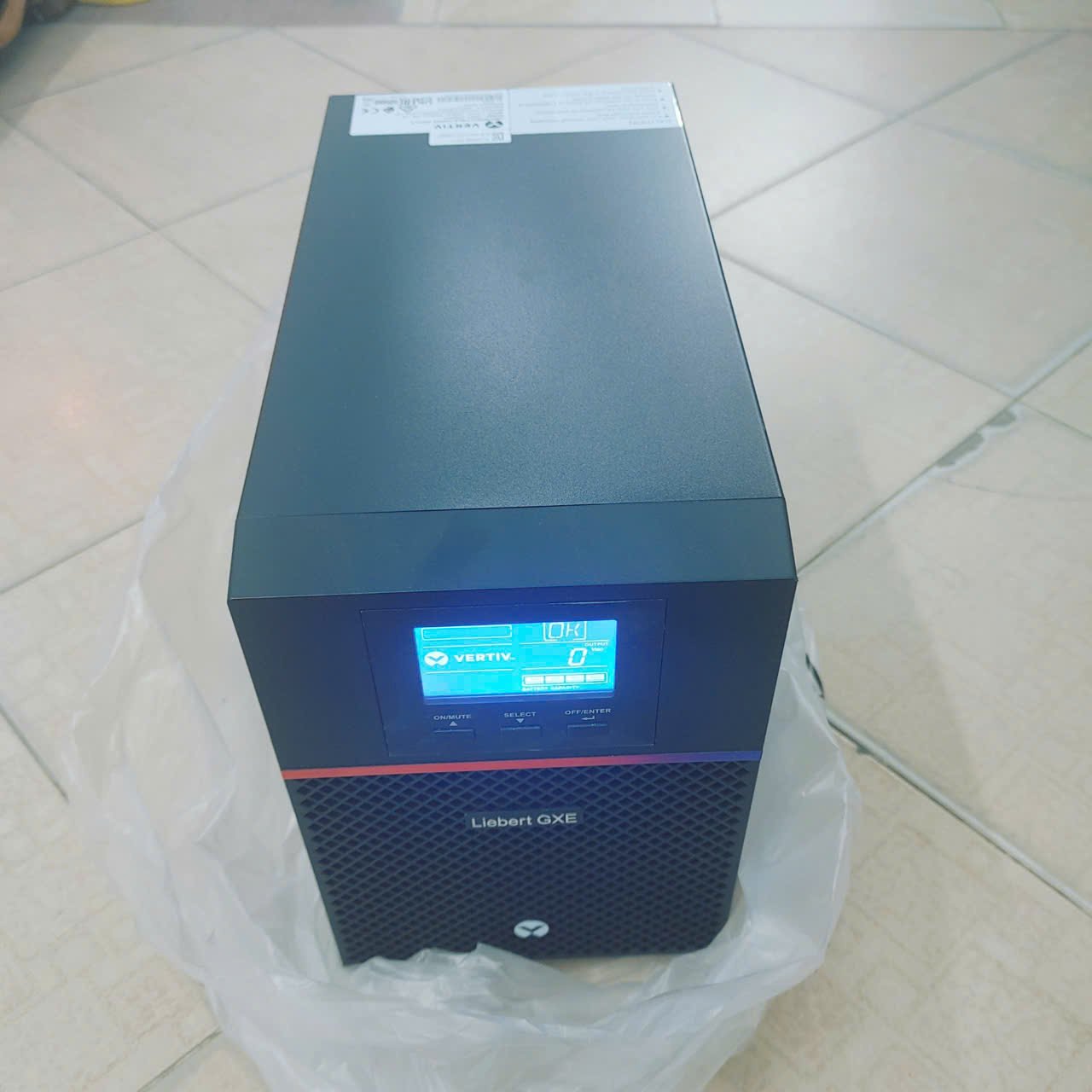
GXE3-6000IRT4UXL
Bộ lưu điện Vertiv Liebert GXE3-6000IRT4UXL là một thiết bị UPS (Uninterruptible Power Supply) thuộc dòng Liebert GXE Series, sử dụng công nghệ Online Double Conversion, cung cấp nguồn điện liên tục và đáng tin cậy cho các thiết bị quan trọng như trung tâm dữ liệu, máy chủ, thiết bị mạng, hoặc các ứng dụng công nghiệp.
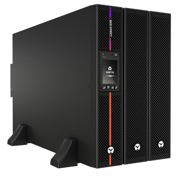
Bộ lưu điện GXE3-10KIRT5UXL
Bộ lưu điện GXE3-10KIRT5UXL là một sản phẩm thuộc dòng Vertiv Liebert GXE Series, sử dụng công nghệ Online Double Conversion, được thiết kế để cung cấp nguồn điện ổn định, đáng tin cậy cho các ứng dụng CNTT quan trọng, đặc biệt tại các vị trí biên mạng (Edge Computing), công suất (10kVA/10kW) với kiểu dáng rack/tower.
Bộ Lưu Điện GXE3-1000IMT
Chúng tôi luôn chú ý đến từng yêu cầu, ngân sách của khách hàng để tư vấn giải pháp tiết kiệm và hiệu quả nhất.
hiệu suất cao, tiết kiệm điện và Tối ưu về giải Pháp


.png)